Spencer
The Spencer method is a general method of slices developed on the basis of limit equilibrium. It requires a satisfying equilibrium of forces and moments acting on individual blocks. The blocks are created by dividing the soil above the slip surface by dividing planes. Forces acting on individual blocks are displayed in the following figure.
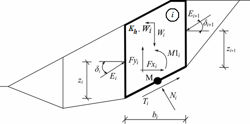 Static scheme - Spencer method
Each block is assumed to contribute due to the following forces:
Wi | - | block weight, including material surcharge having the character of weight including the influence of the coefficient of vertical earthquake Kv |
Kh*Wi | - | horizontal inertia force representing the effect of an earthquake, Kh is the factor of horizontal acceleration during the earthquake |
Ni | - | normal force on the slip surface |
Ti | - | shear force on the slip surface |
Ei ,Ei+1 | - | forces exerted by neighboring blocks, they are inclined from the horizontal plane by angle δ |
Fxi,Fyi | - | other horizontal and vertical forces acting on the block |
M1i | - | moment of forces Fxi, Fyi rotating about point M, which is the center of the ith segment of the slip surface |
Ui | - | pore pressure resultant on the ith segment of the slip surface |
The following assumptions are introduced in the Spencer method to calculate the limit equilibrium of forces and moment on individual blocks:
- dividing planes between blocks are always vertical
- the line of action of the weight of block Wi passes through the center of the ith segment of slip surface represented by point M
- the normal force Ni is acting in the center of the ith segment of slip surface, at point M
- inclination of forces Ei acting between blocks are constant for all blocks and equals to δ, only at slip surface endpoint is δ = 0
The solution adopts the following expressions:
| (1) |
| (2) |
| (3) |
| (4) |
| (5) |
where: | φi | - | angle of internal friction of soil on the slip surface segment |
ci | - | soil cohesion on the slip surface segment | |
αi | - | inclination of the slip surface segment |
Equation (1) represents the relationship between the effective and total value of the normal force acting on the slip surface. Equation (2) corresponds to the Mohr-Coulomb condition representing the relation between the normal and shear forces on a given segment of the slip surface. Equation (3) represents the force equation of equilibrium in the direction normal to the ith segment of the slip surface, whereas Equation (4) represents equilibrium along the ith segment of the slip surface. SF is the factor of safety, which is used to reduce the soil parameters. Equation (5) corresponds to the moment equation of equilibrium about point M, where ygi is the vertical coordinate of the point of application of the weight of block and yM is the vertical coordinate of point M. Modifying equations (3) and (4) provides the following recursive formula:

This formula allows us to calculate all forces Ei acting between blocks for given values of δi and SF. This solution assumes that at the slip surface origin the value of E is known and equal to E1 = 0.
The additional recursive formula follows from the moment equation of equilibrium (5) as:
![]()
This formula allows us calculating for a given value of δ all arms z of forces acting between blocks, knowing the value on the left at the slip surface origin, where z1 = 0.
The factor of safety SF is determined by employing the following iteration process:
- The initial value of δ is set to zero δ = 0.
- The factor of safety SF for a given value of δ follows from equation (6), while assuming the value of En+1 = 0 at the end of the slip surface.
- The value of δ is provided by equation (7) using the values of E determined in the previous step with the requirement of having the moment on the last block equal to zero. Equation (7) does not provide the value of zn+1 as it is equal to zero. For this value, the moment equation of equilibrium (5) must be satisfied.
- Steps 2 and 3 are then repeated until the value of δ does not change.
For the process of iteration to be stable it is necessary to avoid unstable solutions. Such instabilities occur at points where division by zero in expressions (6) and (7) takes place. In equation (7), division by zero is encountered for δ = π/2 or δ = -π/2. Therefore, the value of angle δ must be found in the interval (-π/2 ; π/2).
Division by zero in expression (6) appears when:
![]()
Another check preventing numerical instability is verification of the parameter mα - following condition must be satisfied:
![]()
Therefore before iteration run it is required to find the highest of critical values SFmin satisfying above mentioned conditions. Values below this critical value SFmin are within the area of unstable solution, therefore iteration begins by setting SF to a value "just" above SFmin and all result values of SF from iteration runs are higher than SFmin.
Generally rigorous methods converge worse than the simpler methods (Bishop, Fellenius). Examples with convergence problems include too steep sections of slip surface, complex geometry, a significant jump in surcharge etc. If no result is obtained, we recommend a slight change of input data, e.g. less steep slip surface, input more points into the slip surface etc. or using some of the simpler methods.
Literature:
Spencer, E. 1967. A method of analysis of the stability of embankments assuming parallel interslice forces. Géotechnique, 17(1): 11-26.