Edition 2026
The new edition of the "Truss4" program brings the following new features and improvements:
Drawing Editor
The "Drawing Editor" tool for creating drawings has been added to the "Truss 3D" program. It is a separate window in which users can create drawings and print or export them. When creating drawings, it is possible to combine automatic blocks (roof layout, drawings of individual trusses) and other drawing tools known from previous versions of the program (lines, text, blocks, images, etc.).
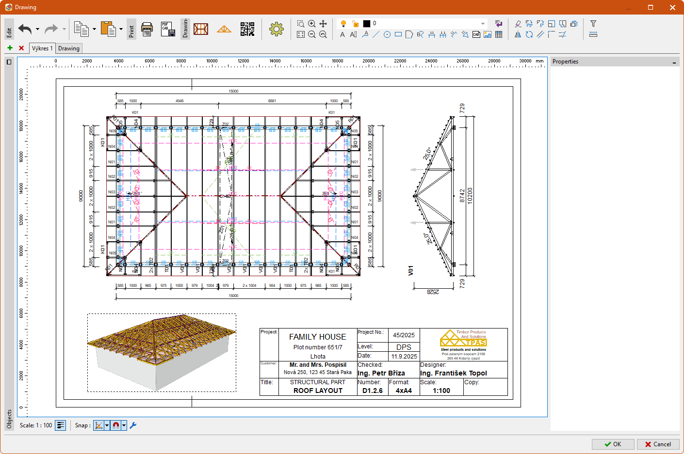 "Drawing Editor" window
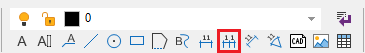
The tool is launched with a new icon in the main toolbar.
The "Drawing Editor" can manage multiple drawings with different scales and formats. Drawings can be inserted and deleted using the buttons next to the drawing tabs. Tools for copying drawings are located in the drop-down list next to the "Copy to Clipboard" command. Drawings can be copied both within a single project and between projects. After this operation, all automatic blocks (roof layouts, trusses, etc.) are automatically updated.
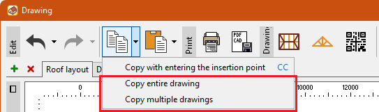 Copying a drawing
The main toolbar contains three types of automatically updated blocks:
- Insert truss layout - inserts a floor plan of the structure, which corresponds to the "Drawing" tool from previous versions. It can display walls, roof planes, trusses, bracing, metalwork, and also the dimensioning.
- Insert truss - Inserting a truss drawing, with the option of dimensioning. The truss type is selected in the properties window, either using the truss list or by clicking on the truss layout.
- Insert QR code - inserts a QR code with a link to the 3D model of the structure on the website.
These blocks are automatically updated whenever the structure changes. Using the "Explode" command, they can be broken down into individual entities and further modified. In addition to automatically updated blocks, other drawing tools that were already available in previous versions of the program can also be used. Tables can now also be inserted.
The drawing properties (paper format, scale, dimension rounding) can be adjusted in the "Options" window.
Created drawings can be printed or saved in a wide range of formats. Export to PDF, CAD formats (DWG, DXF, DGN, DWF), and bitmap images (PNG, JPG, BMP) is supported.
Option to specify multiplicity and thickness for individual production parts
For individual production parts, it is possible to specify a different multiplicity or timber thickness than that specified for the entire truss. Thanks to this adjustment, it is possible, for example, to produce the main load-bearing part as 2-ply and the secondary part as single, or to reinforce the truss using timber that does not correspond to the truss production range.
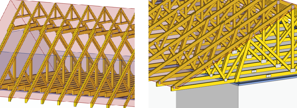 Different number of plies and timber thickness in production parts
The ply option and thickness of the production part can be entered in the "Truss 2D" program in the "Production Parts" section of the control tree. Each truss now has a main production part that uses global thickness and multiplicity. The main production part can be selected using the switch in the second column of the production parts table. For other production parts, the timber thickness or ply option can be changed in the corresponding columns.
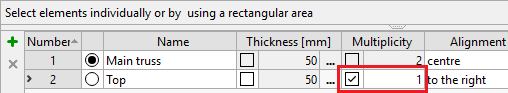 Changes in the "Production parts" table
As a result of these changes, it was necessary to modify the existing behaviour of the program. The main changes are:
- Internal forces and reactions in the "Results" section are now listed for the entire truss, i.e., multiplicity is already taken into account. This differs from previous versions, where values for a single truss ply were listed.
- The structural analysis documentation has been modified accordingly. Internal forces and moments correspond to the entire (multiple) truss. If the multiplicity of all parts is the same, the program also lists the original values for one ply in the outputs.
- Values relating to one ply in the manufacturing documentation for trusses where different multiplicities of production parts are used are no longer relevant for estimating the total volumes. However, the total values given in the documentation are correct.
Export files *.xls do not take into account different multiplicities of production parts.
Member cut-outs
Cut-out is a new feature of the member that allows user to take into account cases where it is necessary to cut out part of the member on site. Typical examples include window and stair openings into attic trusses. However, it can also be used in other cases where it is necessary due to manufacturing or assembly reasons to produce the member differently than it will be used in the structure. The program performs a structural design without the cut-out part, but the resulting manufacturing documentation includes it.
A new "Cut-out" tab is available in "Member properties" where you can insert the cut-out. The method of entry is similar to that for scabs. In addition to the start and end of the cut- out, you can also choose how the load in the cut-out section should be handled. Two options are available:
- Recalculate - the load in the cut-out section will be taken into account in the structural analysis. The shear component of the load on the cut-out part will be evenly distributed to the adjacent parts of the member, and the axial component will be transferred to the part of the member located below. This mode is suitable, for example, for window openings, where climatic loads still act there.
- Ignore - the load in the cut-out part will not be taken into account in the structural analysis, even if it is specified there. An example of use is the stair opening in the level of bottom chord.
These parts are drawn in red hatching in the "Truss 2D" program.
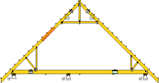 Window opening on the left side
Changing the truss type of selected truss locations
If any truss locations are selected in the "Truss 3D" program, they can be changed to a different type using the "Assign truss from structure" command, which is located in the context menu of the workspace.
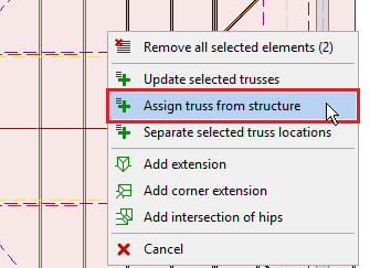 "Assign truss from structure" tool
Automatic design of nail plates in superchords
The program automatically designs nail plates in superchords.
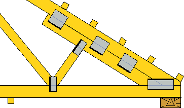 Superchord with nail plates
The design of nail plates is performed automatically. The design can be modified using the parameters located in the "Connection" tab in the "Member properties" window opened for the superchord. You can select the number of plates, the distance from the free ends, as well as the properties of the nail plates. These include the type and size of the plate, maximum utilization, and rotation. If the "Design nail plates" setting is unchecked, the program will not automatically insert the plates.
Changing the prefix of selected trusses
In the "Truss 3D" program, it is possible to rename selected trusses in bulk in the "Results" section. The "Change prefix" tool for renaming is located in the context menu of the truss table. Multiple truss types can be selected by clicking on the first column of the table or graphically on the desktop if the "Graphical selection of truss types" setting is enabled. After selecting the tool, you can enter a new truss prefix in a separate window. The tool can only be used on automatically numbered trusses; trusses with a "custom" description remain unchanged.
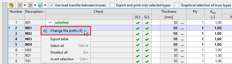 Changing the prefix of selected trusses
Other materials in 3D view
Members made of other materials (steel I-sections, glued laminated timber, etc.) are now displayed in 3D and can be aligned (to the axis, above the axis, below the axis).
 Steel I-beam in 3D view
Reactions from trusses are transferred to these members, so it is possible to determine the internal forces and deformations. Using the *.xml format, they can be transferred to "Fin EC" programs and designed there.
Keyboard shortcuts for the most frequently used functions
Keyboard shortcuts have been added to quickly access the most frequently used commands. They can be used when working on the 2D workspace in the basic windows of the "Truss 2D" and "Truss 3D" programs, as well as in the "Drawing Editor" window. If no other command is active, you can enter the keyboard shortcut for the required command on the keyboard and confirm the entry with the "Enter" key or the space bar. After confirmation, the corresponding command is executed. While typing, the program displays a tooltip with available shortcuts next to the cursor.
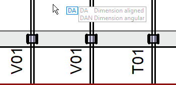 Tooltip with shortcuts
Shortcuts are based on the English terminology. List of available shortcuts:
Tools | LE | Leader | NP | Insert nail plate | |
E | Remove/Erase | L | Line | RC | Reconnect |
CO | Copy | CI | Circle | SY | Align along symmetry axis |
M | Move | REC | Rectangle | WG | Webbing generator |
SC | Scale | PL | Polygon | Truss 3D | |
S | Stretch | SP | Spline | ALO | Add area load |
X | Extend | DA | Aligned dimension | AT | Add attic |
MI | Mirror | D | Linear dimension | PO | Add point |
RO | Rotate | DAN | Angular dimension | TG | Add truss group |
O | Equidistant | DC | Continuous dimension | TU | Add truss |
F | Extend | CA | CAD file | W | Add wall |
TR | Trim/Extend | IM | Image | Drawing Editor | |
Drawing objects | Truss 2D | CC | Copy with insertion point | ||
LA | Edit layers | EC | Edit cuts | R | Insert truss layout |
T | Text | J | Add joint | TU | Insert truss |
MT | Multi-line text | ME | Add member | Q | Insert QR code |
Provision of automatic member design
In the "Limit values" section of the "Project/truss options" dialog box, you can enter the value for the "Provision of automatic member design". The value is entered as a percentage. During the automatic timber design, this value is then subtracted from the maximum allowable utilization. However, the reserve is not taken into account in the final verification. The program therefore designs members for reduced utilization, but the final assessment is performed as usual. This reserve can be used to resolve cases where automatically designed members do not satisfy in the final verification due to the redistribution of internal forces after the design of nail plates. This setting can be used, for example, when creating price quotes, where speed is preferred over design accuracy. For normal cases, it is sufficient to enter a provision in lower percentage values.
Member loading width
In the "Member Properties" on the "Profile" tab, you can enter the loading width that will be used for the given member instead of the global loading width.
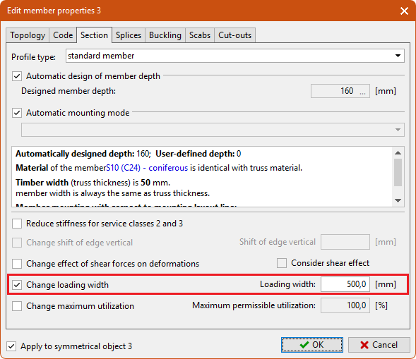 Member loading width
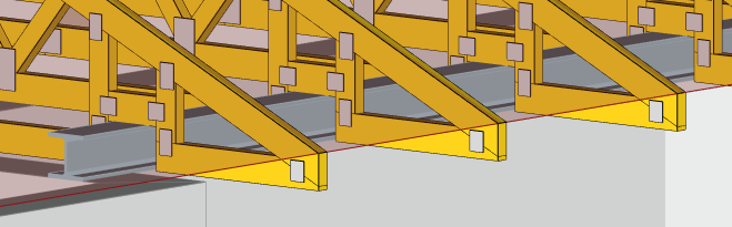
This setting can be used to address cases where a specific member takes on loads from a different area than the rest of the structure. The most common case is trusses with intermediate ceiling joists, where the bottom flanges of the truss have a smaller load-bearing width than the other members.
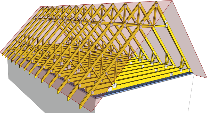 Attic trusses with intermediate ceiling joists
Non-structural members
Non-structural components can be used to model secondary parts of trusses. These are members that are not included in the structural analysis and therefore do not contribute to the overall load-bearing capacity of the truss. They should therefore only be used for secondary elements or elements with significant weakening that cannot perform a load-bearing function. Examples include slope wedges and similar elements. Structural components are drawn in grey on the workspace.
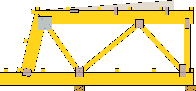 Non-structural wedge
Any member can be changed to a non-structural one by assigning the code "10 - structural". After changing a member to a non-structural one, this member will no longer be created in the truss analysis model and will not be included in the subsequent structural analysis. The load specified for the member remains in the structure, but is no longer taken into account. Therefore, it will not be reflected in the resulting reactions.
The nail plates connecting the non-structural members are only analysed for transport forces.
Extended analysis log
For better orientation during the design process, the information displayed during automatic truss design in the "Truss 3D" program has been expanded. In addition to an overview of the current status of the calculated trusses, dependencies based on load transfer are also listed.
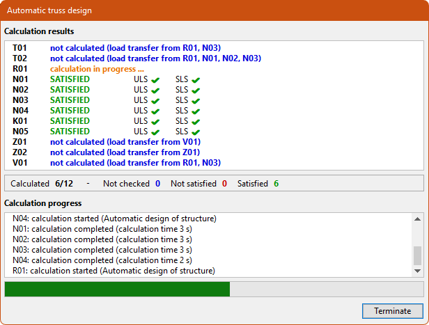 Improved analysis log
Continuous (Chain) dimension
When dimensioning manually, it is now possible to use the "Continuous dimension" tool. This tool allows users to enter multiple dimensions in a single step. First, the dimensioned points are entered, followed by the position of the dimension line.
 "Continuous dimension" tool
"Explode" tool
A new "Explode" function is available in the "Tools" bar. This command can be used to explode any inserted block into individual entities (lines, texts, etc.).
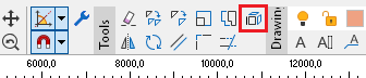 "Explode" tool
Documentation of the T-brace analysis
In the "Structural analysis" document, it is possible to enable the "T-braces" item in the "Member analysis" section. This item adds a table to the document containing the main inputs and results of the T-brace analysis. These include, in particular, the design value of stabilizing force, the dimensions and stiffness of the T-brace, the connection parameters, and finally the total and required stiffness of the whole system.
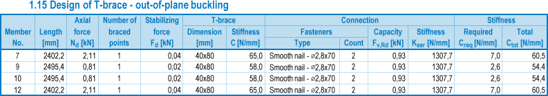 T-braces in the "Structural analysis" document
Extended report of horizontal deformations in supports
The program lists the maximum horizontal deformation in the supports also for the final combinations. Previously, only the maximum deformation from characteristic combinations was listed. The list can be found in the table of maximum reactions for load combinations.
Export format for TCT saws
The option to export members to *.web format for TCT saws has been added.