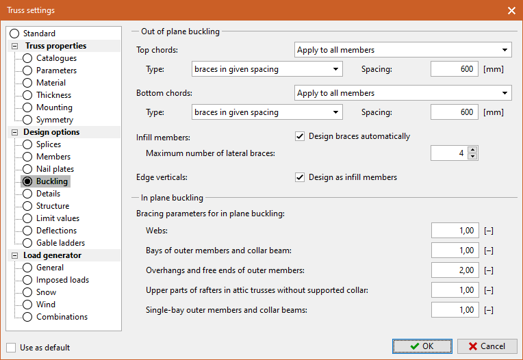
Buckling
In this frame are the settings that relate to the buckling analysis of the members in compression. The frame is divided according to the buckling orientation into two parts " In-plane buckling" and " Out-of-plane buckling".
Out-of-plane buckling
This section is focused on the out of plane buckling properties of the truss, i.e. in the direction where the stability of the structure is provided by the lateral bracing. The settings located here therefore affect the positioning of the lateral braces.
For the "Top chords" and "Bottom chords" (which include the collar beams) it is possible to select whether the lateral bracing to prevent buckling should always be inserted ("Apply to all members") or only to members that are subjected to compressive forces ("Apply only to compressive members"). The style of inserting the bracing can then be selected:
Braces in given spacing |
|
Continuous brace |
|
Automatic design of braces |
|
For " Infill members" (diagonals and inner verticals) it is possible to switch on the automatic design of lateral braces. Within this automatic design, the program adds braces to the member if the member fails due to the out-of-plane buckling stresses. The maximum number of braces per member can be adjusted by the user, the default value is 4.
If the topology of the structure is not suitable for the use of lateral braces, they can be replaced by T-braces attached along the braced member using the "Replace longitudinal braces by T-brace" setting. The setting is useful in structures with variable webbing of individual trusses or in structures with a large truss spacing.
 T-brace on web
For T-braces, it is possible to specify the type of fastener to be used in the design. It is then possible to select whether the fastener size and the cross-section of the T-brace should be calculated automatically or whether the program should only check the size defined by the user. When designing T-brace automatically, the program uses the current range of timber and fasteners, which can be selected in the "Catalogues" section.
The "edge verticals" are considered as standard outer members and share the setting (method of brace insertion and distance between braces) with the top chords. If the setting "Design as infill members" is checked, the edge verticals are treated as diagonals and internal verticals. In this mode, the reinforcements on the edge verticals are then determined by number, not by distance.
In-plane buckling
In-plane buckling is the direction of buckling where the buckling characteristics are determined by the shape of the truss and cannot be influenced by the addition of lateral braces. This section allows user to enter the coefficients that are used to determine the buckling length of the members when checking the in-plane buckling of the truss. The coefficients are multiplied by the basic length of the segment, resulting in the buckling length. This procedure substitutes the exact calculation of buckling lengths from the inflection points of the deflection curve, which is not feasible under the conditions of a conventional structural program. With a value of 1.0, the buckling length is equal to the basic length of the member or member part. This value is mainly used for members whose connection to the structure is close to pinned. However, it can be used almost anywhere besides overhangs and cantilevers as a relatively safe value. Values less than 1.0 find use in cases of members or their parts with significant end moments and result in a buckling length that is shorter than the basic length. This may be the case, for example, for single bays of continuous outer members with linear transverse loading, which prevents different orientation of deformation in odd and even bays. Values greater than 1.0 are mainly used in the case of missing or insufficient connection at one of the ends, the resulting buckling length being longer than the basic length. Typical applications are cantilevers and overlaps. The coefficients are entered separately for subsequent members or parts thereof:
Webs |
|
Chords including collar beam |
|
Overhangs |
|
Upper parts of rafters in attic trusses without supported collar beam |
|
Chords with one bay including collar beam |
|
 Part "Buckling"